In spontaneous Raman scattering, only one laser beam at a frequency ωp illuminates the sample and the signal is generated at the Stokes and anti-Stokes frequencies, ωs and ωas, respectively, due to inelastic scattering. In SRS, however, two laser beams at ωp and ωS coincide on the sample. When the difference frequency Δω=ωp-ωS (also called the Raman shift), matches a particular molecular vibrational frequency Ω, amplification of the Raman signal is achieved by virtue of stimulated excitation of molecular transition rate r. r ~ σRaman· np· (nS +1) σRaman is the (Raman-shift dependent) Raman scattering cross-section of the molecule and np and nS are the number of photons per mode in the pump and Stokes fields, respectively. In the absence of the Stokes-beam (nS=0), the unity in the equation above accounts for spontaneous Raman scattering. Under our typical excitation condition nS is, however, bigger than 10^7; hence, stimulated Raman scattering provides amplification at the vibrational transition rate. As a consequence of the amplified energy transition rate, the intensity of the Stokes beam, IS, experiences a gain, ΔIS, (stimulated Raman gain, SRG) and the intensity of the pump beam, Ip, experiences a loss, ΔIp, (stimulated Raman loss, SRL). Either ΔIS or ΔIp can be used as vibrational contrast for SRG and SRL microscopy, respectively.
SRS cannot occur when Δω does not match any vibrational resonance that absorbs the difference energy from the fields. Thus, SRS does not have a nonresonant background signal. The intensity of SRG or SRL is described by ΔIS ~ N · σRaman· Ip· IS and ΔIp ~ - N · σRaman· Ip· IS , where N is the number of molecules in the probe volume. As in two-photon microscopy, the nonlinearity of SRS in the overall excitation intensity is the basis for 3D sectioning, which allows for point-by-point three-dimensional imaging of thick specimens.
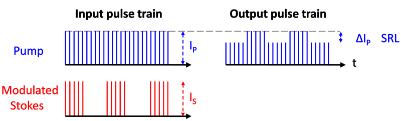
In contrast to the CARS signal that is generated at the anti-Stokes frequency, SRG and SRL occur at the frequency of the excitation beams. Although the Raman signal is greatly enhanced, SRL and SRG are relativity small compared to the intensity of the excitation beams (ΔIp/Ip and ΔIS/IS <10-4) under biocompatible illumination conditions and are thus buried in the laser noise. Realizing that laser noise occurs primarily at low frequencies, a high-frequency phase-sensitive detection scheme is critical. As shown in Fig.1, one can modulate the intensity of the Stokes beam (>1MHz) and detect the resulting intensity modulation of the pump beam due to SRL at the same frequency with a lock-in amplifier. The lock-in amplifier signal can be directly fed into the D/A-converter of the microscope. Similarly, SRG can be measured by modulating the pump beam and detecting the Stokes beam. The high intensity laser light can best be detected with a large-area photodiode with high reverse bias voltage to allow the time-response needed from MHz-modulation. With this approach, ΔIp/Ip as small as 10-8 can be achieved with a 1s time constant. This is close to the shot-noise-limit. |
We detected SRL instead of SRG because the responsivity of the photodiode used is higher for the pump than for the Stokes beam. Collinear pump- and Stokes-beams are focused with a high numerical aperture objective onto a common focal spot (Fig.2). To detect the pump- or Stokes-beams in the forward direction, we recommend using a condenser with a numerical aperture higher than that of the excitation objective, in order to minimize unwanted background due to cross-phase-modulation, which may yield a spurious background.
Epi (backward) detection is possible in turbid samples because multiple scattering events redirect a significant portion of the forward propagating pump and Stokes beams to the backward direction, which can be collected with the same excitation objective lens. The excitation light is separated from the detection light with a polarizing beam splitter and quarter-waveplate in a double-pass geometry.
|
|
Fig.3: SRS tissue imaging of fresh mouse skin. For the acquisition of this image stack in mouse ear, SRL image contrast was tuned into the CH2-stretching vibration. As such, lipid rich structures of the skin were highlighted. From top (beginning of the movie) to bottom (end of the movie):
- Polygonal intercellular space of the stratum corneum
- Viable epidermis with hair follicle
- Sebaceous gland
The image stack was taken on fresh tissue, without any preparation or labeling. |